RS Flip-flop:
The circuit diagram and truth table of RS flip-flop are given below:

The truth table for SR flip-flops is:
|
S |
R |
Q(t) |
Q(t + 1) |
|
|
0 |
0 |
0 |
0 |
No changes |
|
0 |
0 |
1 |
1 |
|
|
0 |
1 |
0 |
0 |
reset to 0 |
|
0 |
1 |
1 |
0 |
|
|
1 |
0 |
0 |
1 |
set to 1 |
|
1 |
0 |
1 |
1 |
|
|
1 |
1 |
0 |
Invalid |
Don’t care |
|
1 |
1 |
1 |
Invalid |
S = R = 0 is the normal resting condition of the SR flip-flop.
It has no effect on the output state of the flip-flop. Both Q(t) and Q(t+1) outputs remain in the logic state they were in prior to this input condition.
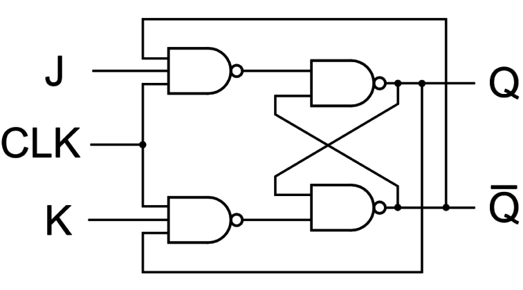
JK Flip Flop:
The circuit diagram and truth table of JK flip-flop are given below:

Truth Table for J-K flip flop is as follows:
|
J |
K |
Q |
Q̅ |
Description |
|
0 |
0 |
0 |
0 |
No Change |
|
0 |
0 |
0 |
1 |
No Change |
|
0 |
1 |
1 |
0 |
Reset to 0 |
|
0 |
1 |
0 |
1 |
Reset to 0 |
|
1 |
0 |
0 |
1 |
Set to 1 |
|
1 |
0 |
1 |
0 |
Set to 1 |
|
1 |
1 |
0 |
1 |
Toggle |
|
1 |
1 |
1 |
0 |
Toggle |
Observation:
From the above truth table, if the two inputs are high, then the output of SR flip flop is Don’t care but JK flip flop provides Toggled output.
Click here to submit your answer.
s